bench-verified · firmware on real hardware
ET-160
- Built for:
- One tractor, converted from gas to electric end to end — the drivetrain, the safety wiring, and a cockpit that reads like a vehicle, not a hobby project.
- Not built for:
- Anyone who wants a kit. Every wire, current limit, and fail-safe here was decided for this machine; none of it is a product you can buy.
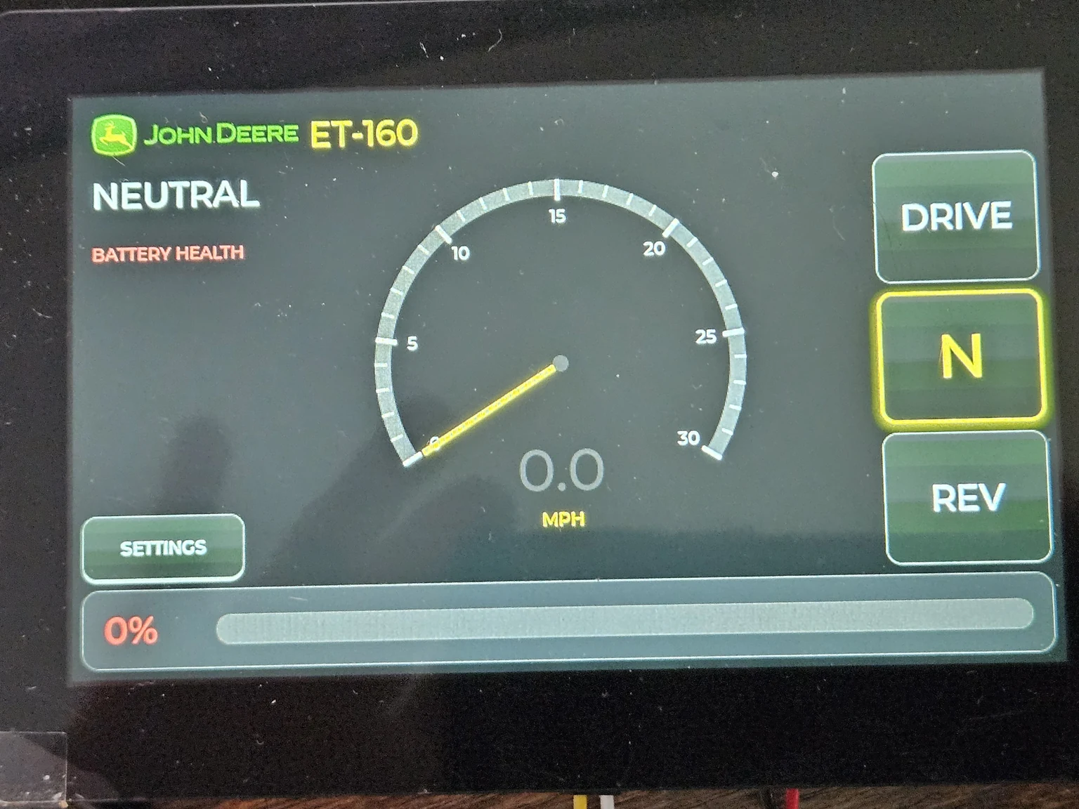
A 48-volt battery, a motor controller meant for electric skateboards pushed to do real work, two pedals wired straight to the controller so a software crash can never take the brakes, and a touchscreen dash I wrote in C++. It is designed, wired, and flashed; the firmware runs on the real screen and talks to the real controller over CAN. It has not yet turned a wheel on the tractor — that is the next step, after the motor is bolted in.
The problem
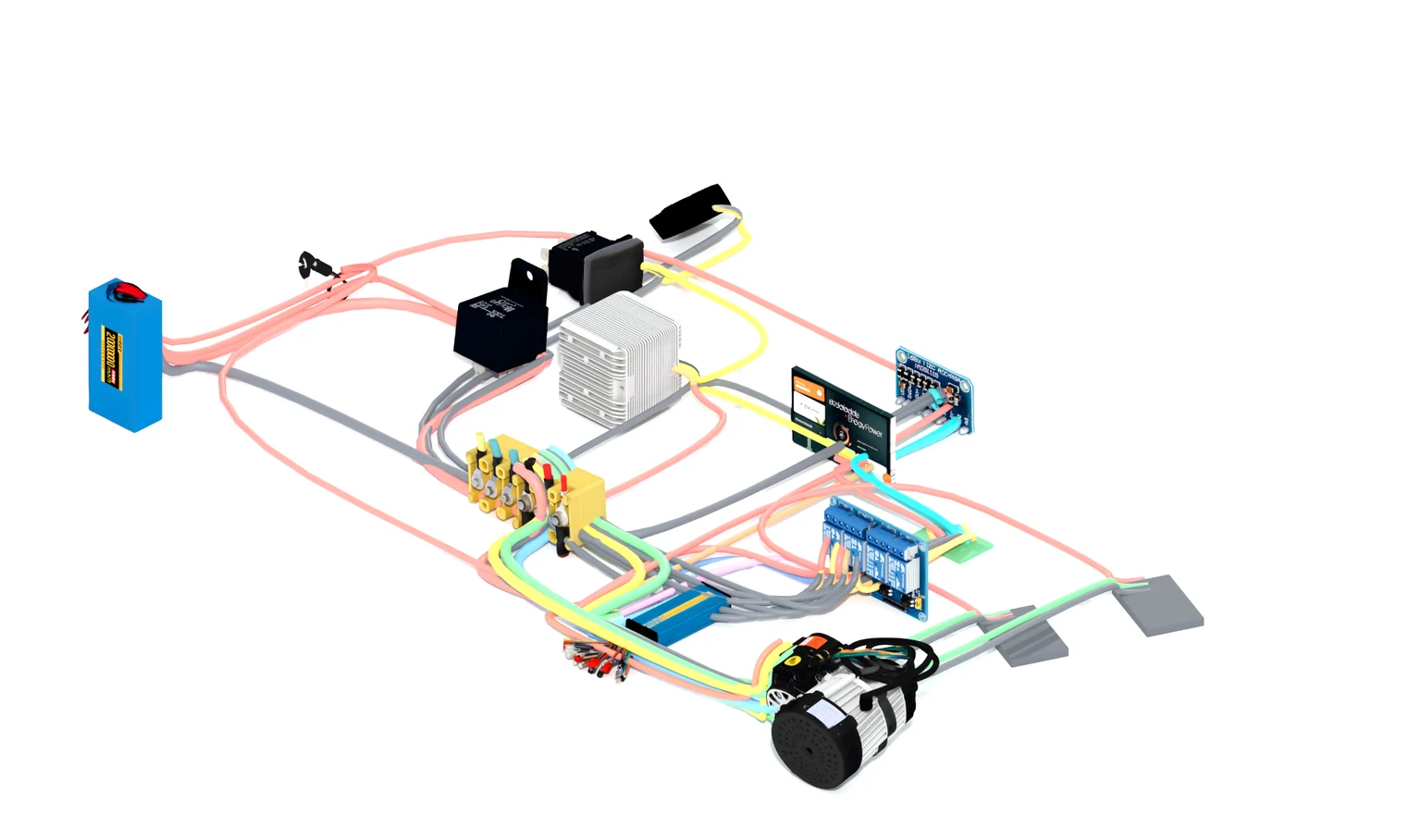
Converting a gas tractor to electric is mostly not the motor. The motor is the easy part. The hard part is everything that keeps 48 volts of direct current from doing something stupid: a contactor that can weld shut under load, a screen that could hang while you’re moving, a pedal signal that has to mean the same thing every single time. A car company solves this with a hundred engineers and a wiring harness the size of a person. I had one tractor and a spreadsheet.
So the whole build is organized around one idea — the dangerous paths are physical, and the convenient paths are software. Braking and throttle are hardwired to the controller. The dash is allowed to be clever because it cannot touch anything that stops the machine.
Decisions
deleted
The main contactor. A mechanical relay switching 48V DC under load will eventually weld its contacts closed — and a relay welded closed is a tractor that won’t turn off. The controller already enforces current limits in firmware and coasts to neutral when power is cut, so the relay was doing a dangerous job badly. It came out of the diagram entirely; a fused enable line replaces it.
hardwired
Both pedals straight to the controller’s analog inputs — right pedal throttle, left pedal regenerative brake. Not through the dash, not over the bus. If the screen hangs, freezes, or reboots, the pedals still work, because the pedals were never talking to the screen. The dash only ever selects gear and reads telemetry; it is never in the path that makes the machine go or stop.
kept
One netlist as the single source of truth — 51 wires, 20 components — and a small verifier that checks the firmware, the spreadsheet, and the controller’s pin map all agree before anything gets powered. When I rename a pin in code, the check fails until the diagram catches up. It is the only reason an eleven-day solo build of high-voltage wiring didn’t drift into a mistake I couldn’t see.
System
Power runs in a straight line and the controls hang off it. The battery feeds a DC-rated fuse, a bus bar, then the controller, then the motor’s three phases. The dash is a separate world: it sits on a CAN bus with the controller, sends gear selection, and reads back pack voltage, temperature, and current at 50 Hz. The pedals never appear in that conversation — they go straight to the controller’s analog inputs.
| Layer | Implementation | Purpose |
|---|---|---|
| Pack | 48V nominal (35.8–54.6V) | Drive energy · 35A BMS limit |
| Controller | FLIPSKY FSESC 75100 Pro | Motor drive · current limits in firmware |
| Motor | 1000W Hall-sensored | Differential drive · 30A / −15A regen |
| Dash MCU | ESP32-S3 · LVGL v8 | Gear select · live telemetry · 800×480 |
| Comms | CAN bus · TWAI · 500 kbit/s | Dash ⇄ controller · big-endian VESC frames |
| Pedals | 2× analog → controller ADC | Throttle + regen · never via software |
Where it stands
Bench-complete and paused before install. The dash firmware is flashed and running on the real panel; the controller is configured and its settings written to flash; the CAN link is up, reading live pack voltage, temperature, and current. What’s left is physical — motor detection, a direction test, and the speed cap — all of which wait until the motor is permanently mounted on the tractor. It has been designed, wired, and proven on the bench. It has not yet been driven, and the copy here won’t pretend otherwise.
Acknowledgments
ET-160 stands on the VESC project and its CAN protocol, LVGL for the cockpit, the Arduino-ESP32 TWAI driver, and the conviction that on anything carrying 48 volts, the boring safe path should be a wire and the clever path should be software.
← Index